Poor Man’s Café Racer
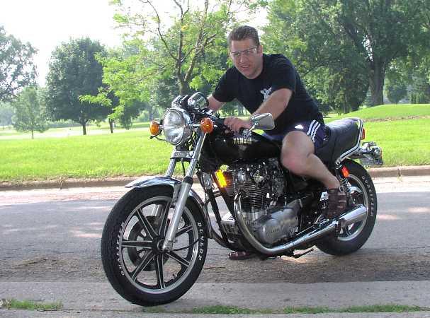
A Farrell Hope Conversion
fhope@new.rr.com
The following is a description complete with pictures of how I converted my 1981 Yamaha XS650 into a café racer at minimal cost. For the rear-sets I used the foot-pegs off a '82 750 Maxim ($55), which have integral mounting brackets, shift and brake levers; these gave approximately 13” rear-set. For the handle bar I used a conventional 2” rise straight bar ($25), installed inverted and cut narrow; this placed the grips about exactly where they would be with a clip-on. For the kick start I took a used one from the bin at the salvage yard ($15), I don’t know what it is from but there were a half dozen in the bin so it must have been a pretty common bike. Total cost of the conversion including hardware store sundries was less than $100. Skill and tools required are those of your average shade-tree mechanic. All dimensions and thread sizes are approximate because I am not going to pull it all to pieces to measure, except for the lug nut size which is important and quoted correctly. This being the litigious happy USA I will also tell you that anyone who does this modification does it at their own risk, I claim no qualifications in this area and take no responsibility whatsoever for the mechanical integrity and safety related aspects of anything I describe. Be warned. And use Loctite everywhere.
I’ll break the job into three sections:
- Left side rear-set
- Right side rear-set
- Handlebars
Left side rear-set
Remove and discard the existing rider pegs and brackets. Leave the studs on the frame in case you ever want to return the bike to the original configuration, but reinstall the acorn nuts on the studs for safety and a finished look. Remove the gear lever and discard. Remove the nut that holds the muffler to the frame and remove the passenger foot-peg, save these for re-use.
|
|
|
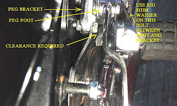
Mount the new Maxim peg assembly to the stud that held the passenger foot-peg. The stud goes through the hole at the lower rear corner of the Maxim peg bracket. I had to drill the hole slightly larger, but the metal is soft. Now here comes one of the trickier problems, but one with an elegant solution. The hole in the Maxim peg bracket is counter-bored for half the thickness of the bracket, so there is enough stud thread exposed for a good grip, but it is all in this counter-bore because the stud does not project beyond the surface of the bracket. The counter-bore is not big enough in diameter to accept a normal nut, and in any case you could not get a wrench on it. The solution is to use one of the fancy lug nuts that hold a mag wheel onto a car, these have a threaded projection that goes into the counter-bore. Size needed is 12MM by 1.25 pitch. I got two chromed ones for nothing by rooting through the 44 gallon drum of old wheel nuts at the local tire and mag wheel shop, but if you live in Podunk Iowa you may have to order them at your local NAPA store for about $3 apiece. 12MM by 1.25 pitch is not a common size, but it exists.
The Maxim peg bracket has to be rigid; this was accomplished by bolting a metal strap from the front of the Maxim peg bracket to the stud that holds the muffler bracket. To make these I used what I happened to have handy in my garage; you need a flat strip of metal 1” wide by approx. 3/16” thick by approx. 3.5” long, with suitable holes drilled in either end. It attaches to the Maxim peg bracket by a bolt approx. 8mm dia. X 2.5cm length, passed through the slot in the bracket that allows fore-and-aft adjustment of the gear lever position. The strap needs to be bent into a slight gentle S to fit properly.
Passenger Footrest Picture 1 again
The pillion passenger peg is then mounted to the hole in the upper rear of the Maxim peg bracket using a bolt approx. 8mm dia. X 2.5cm length, and suitable large washers. The holes can’t line up exactly, 8mm dia. is the largest bolt that will pass.
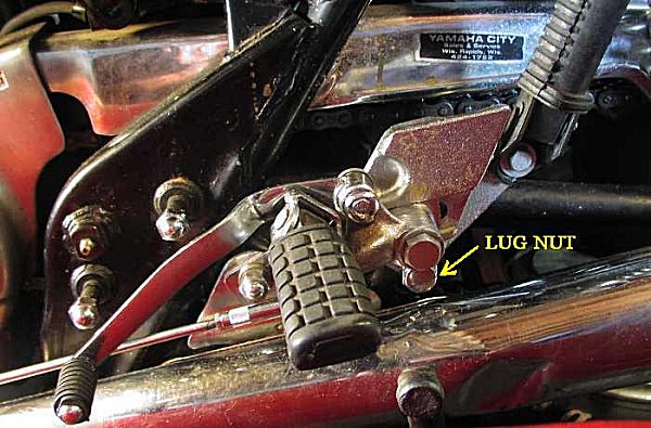
Gearshift lever Picture 4
In order for the lever to move freely it must clear the head of the bolt that connects the bracket to the bracing strap described above. This is accomplished by shimming the peg away from it’s bracket using a large washer in the slot under the peg foot, the gear shift lever is mounted off the peg and moves outward with it.
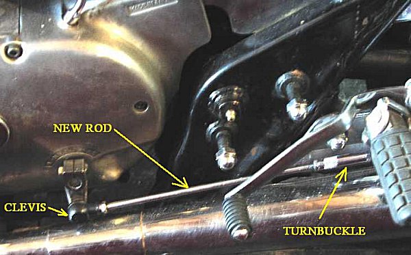
Gearshift Linkage Picture 5
The rear-set is now about 13” back of the original foot-peg position; the linkage rod that comes with the Maxim peg is much too short. No sweat, just replace the piece between the turnbuckle and the clevis that slips over the gear shift shaft coming out of the transmission with a rod 6mm dia x 23cm long, tapped to 6mm thread on both ends. Once again I used what I had available; a nice piece of chromed dishcloth rack. She’ll never notice.
Right Side Rear-Set
This is much like the left side with the following differences:
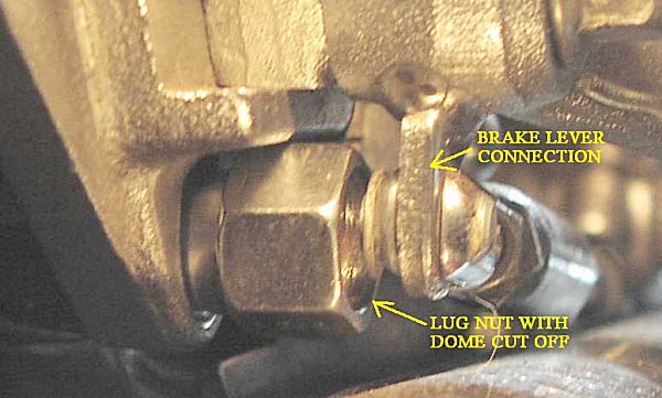
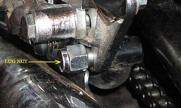
Mounting Nut Picture 6
The brake lever mounting does not allow enough clearance for the lug nut, so the domed part of the lug nut needs to be hack-sawed off.
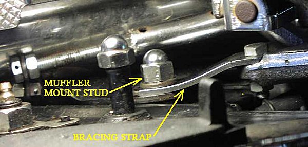
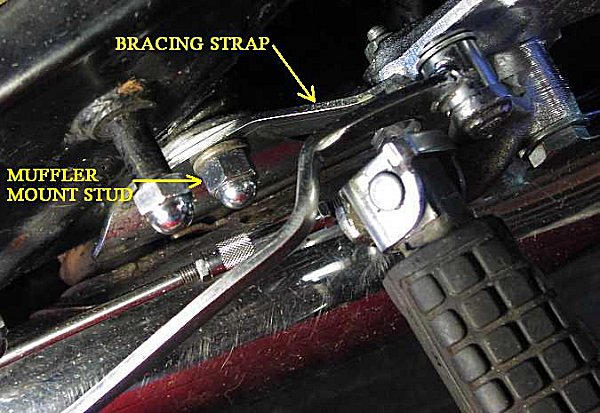
Bracing Strap Picture 7
The strap is not exactly the same size as the one on the other side, and the S is a little different. Don’t make them together.
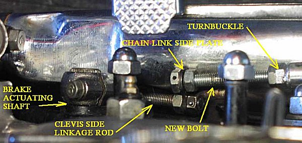
Brake Linkage Picture 8
The brake linkage needs to dogleg around the muffler. This was probably the trickiest part of the whole conversion. Remove the entire right hand exhaust and muffler system. Remove the old brake lever and discard. On the new brake lever unscrew the linkage rod on the clevis side from the turnbuckle. The offset linkage is then made as follows. Take one link of #530 motorcycle chain, as used on an XS650, and dismantle it, the steel side-plate of this link will be the offset. Put an 8mm nut on the linkage rod you have removed from the turnbuckle, and thread it about a half-inch onto the rod. Then pass the rod through one of the holes on the chain-link side-plate, and put on another 8mm nut. Turn that nut till it is just flush on the rod. Now back the first nut towards the end of the rod and tighten, gripping the side-plate of the chain-link firmly between the two nuts. Then for safety drill through outside nut and rod and put in a small cotter pin.
Next thread an 8mm dia. X 9cm long bolt all the way through the other hole in the chain-link side-plate, to extend to the opposite side to which the above linkage rod is extending. Thread on an 8mm nut, and tighten the chain-link firmly between the head of this bolt and the nut. You now have a dogleg linkage of the right length. Thread the end of the bolt into the turnbuckle, mount the clevis onto the brake shaft, and adjust the turnbuckle. You may have to slack some of the nuts, adjust the angle of the chain-link side-plate, and retighten them, when you reinstall the muffler.
Reinstalling The Muffler Picture 8 Again
On the Dunstall mufflers I would have had enough clearance between the muffler and the bike frame for the clevis. On the standard mufflers I did not, I had to flatten the muffler slightly where the clevis resides. This flattened area is not visible when the muffler is installed.
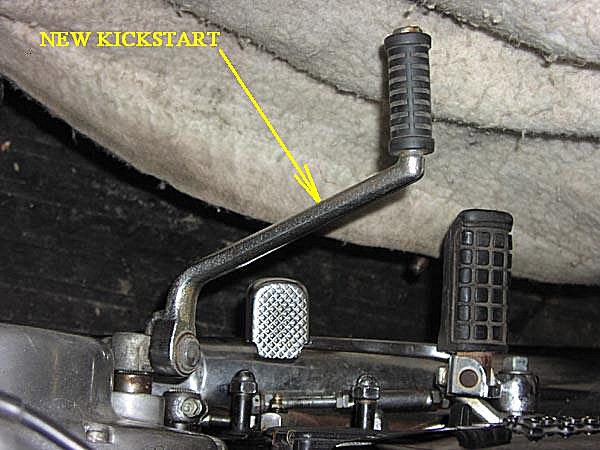
Kick-start Picture 9
The original kick-start does not quite clear the new brake pedal. I used a kick-start pulled from the bin at the salvage yard, obviously a very common one because he had a number of them in the bin. I have since identified it as the kickstart that came with the three Cylinder Yamaha models.
Cutting To As Narrow As Possible Picture 10
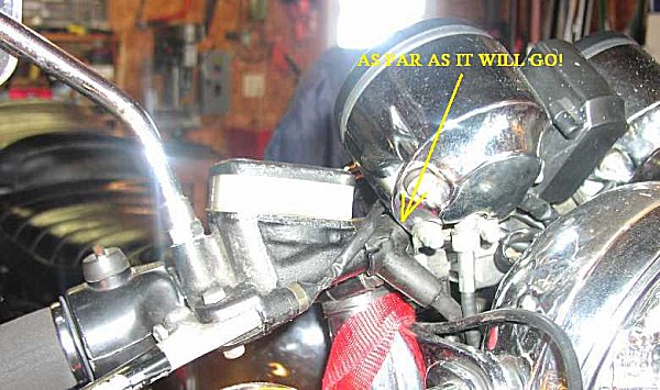
Remove all levers etc. from handlebars, and remove bars. Remove headlight sealed beam assembly from headlight shell. Place new 2” rise straight bars in inverted position and clamp temporarily. Slide on right hand side lever and throttle. Slide lever up towards headlight and rotate levers and handlebars to your comfort, bringing in brake lever as close as you can to headlight assembly. Clamp temporarily. Slide throttle all the way on. The amount of handle bar showing between the throttle and the brake lever clamp is what you can cut off the ends of the handle bars. Remove throttle and brake assembly and cut off the same amount off each bar end. The clutch side does not have as much equipment mounted, so it will be OK as long as it has the same length as the throttle side. You will end up with about 9” of straight bar on each side.
NOTE: I FOUND THE BARS DESCRIBED HERE UNCOMFORTABLE, AND CHANGED THEM FOR A SET OF CLUBMAN BARS, AVAILBLE NEW AT DEALERS FOR ABOUT $20. ALL CABLE, HOSE AND WIRE ROUTING DESCRIPTIONS STILL APPLY EXACTLY AS WRITTEN AND SHOWN.
Routing hoses, cables and wiring
This is how you handle the extra length of the cables and hoses.
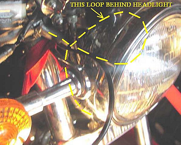
Brake Hose Picture 11
Form a loop with the brake hose before sliding the brake lever assembly on to the handlebar. This loop slides neatly behind the headlight, the hose therefore goes down, around, up, and down again into the manifold block between the forks. You do NOT have to disconnect the hose.
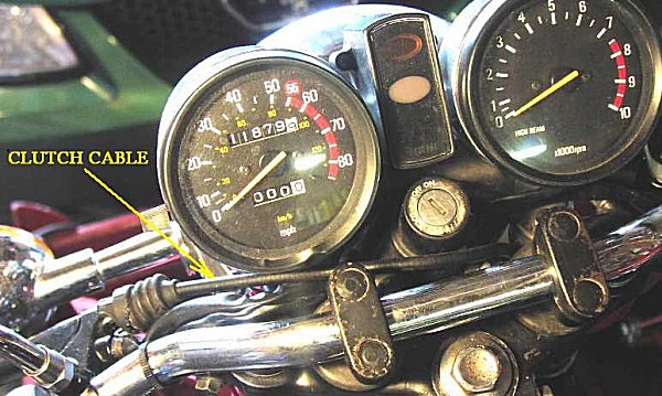
Clutch Cable Picture 12
Disconnect cable from lever. Mount lever and rubber hand-grip, and clamp lever in final position (For what it’s worth, I use hair-spray inside the handlebar rubber grips. It helps them slide on easily and then dries to a glue that is adequate but easily overcome when you want to remove them). Route clutch cable from where it emerges left of bike steering head, through behind the headlight to the right of the bike, bring it up inside the right headlamp bracket, then bring it back above the triple crown clamp and behind the ignition switch housing to the clutch lever. Re-attach to lever. Attachment will not be easy because a lot of slack is lost on the curves, but it is do-able WITHOUT having to slack the clutch cable down at the gearbox. All clutch cable curves are gentle and OK, and it is very neat.

Throttle Cable Picture 13
Route forward under indicator light, then back over indicator light, over right headlight bracket and down under headlight. The loop extends quite far forward, but looks fine.
Electric wiring
Pull all excess handlebar wiring into headlight shell, then reinstall headlight sealed beam assembly.
Now try to find neutral while stopped. If you thought it was difficult before, just wait.
Farrell Hope
December, 2002
Retrieved from "http://650wiki.org/index.php/12.02._Cafe_Racer_Idea"