
INSTALLATION GUIDE FOR SPARX Alternator to fit Yamaha 650 twins
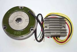
This unit replaces the original excited field rotor, stator and voltage regulator with a permanent magnet rotor and an epoxy encapsulated stator as well as a solid state regulator/rectifier.
There are two units available, a single phase unit and three phase.
Single phase provides 160w of power at 3000 RPM and is an excellent choice for regular road use or running with a capacitor in place of the battery.
Three phase provides 220w of power at 3000 RPM and is useful when extra accessories are installed. Three phase requires a battery in circuit to operate properly.
You will need these tools :
1. Impact type screw driver to remove alternator cover and stator assembly
2. Metric wrench set to remove rotor nut
3. Allen key set to install new stator mounting ring
4. Yamaha rotor removal tool # 35-0040
Step 1.
Disconnect the battery. Remove the shift lever. Remove the Left hand engine cover retained by the six securing screws.
Step 2.
Disconnect the stator wire harness where it connects to the main wire harness. Remove the old stator assembly by slacking the two Philips head screws securing it to the main engine case. Lift the unit off the crankshaft mounted rotor.
Step 3.
Remove original Alternator rotor from crankshaft using Yamaha puller # 35-0040
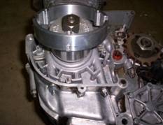
Step 4.
Assemble the Sparx rotor to the crankshaft using the original key and the new securing nut provided. Torque to 30 lb.ft. (4.1 kg.m.)
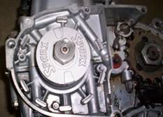
Step 5.
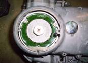
Install stator mounting ring taking care to line up the locating pin with the groove in the housing. Use the 6mm screws provided.
Step 6.
Install new Sparx stator using 8mm screws provided.
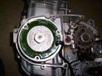
Step 7.
It is very important that there be an air gap between the rotor and stator. Using a feeler gauge check for clearance at four different locations at 3/6/9/12 o’clock positions. The clearance must be .008” inch minimum between the rotor magnets and the stator poles. If clearance is less than this slack the two 6mm screws securing the stator adaptor ring and reposition it to get the required clearance. Rotate the crankshaft 90 degrees and repeat the measuring process to verify consistent clearance.
Note: If the rotor comes in contact with the stator while in operation catastrophic failure may result.
If you do not feel confident in completing this part of the assembly process, please take your machine to a qualified technician to complete the assembly process.
**Single & Three phase boxes***
Due to the sensitive nature of both the single and three phase boxes it is VERY
important to fit spark plug caps of the 5000ohm resisted type. Failure to do so
will cause overloading.
Step 8.
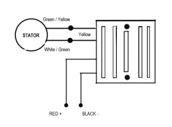
Install the solid state regulator box in a well vented area. It is important that the box not be exposed to excessive heat. It is normal for the box to get hot in operation. Wire diagram for single and 3 phase box:
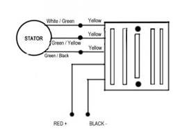
Three Phase wire diagram:
Step 9.
Connect the new regulator/rectifier red wire to the red wire in the original harness. Tape off the rest of the wires that went to the original alternator as these are no longer required. The black wire from the new regulator must be grounded to the motorcycle engine or frame. Alternately the red wire may be connected directly to the Positive (+) terminal of the battery. Make sure to secure the alternator wires so they are not damaged by the drive chain.
Step 10.
Reuse the rubber grommet from the old harness to seal the alternator cavity. A dab of RTV Silicone should be used to ensure that debits do not enter the alternator cavity. Refit the outer cover taking care not to pinch the alternator wires.
Step 11.
Reconnect the battery. Start the engine. Using a volt meter across the battery terminals check alternator output. A reading of 12.7-13.5 volts should be recorded depending on the ability of the battery to accept a charge.
Note: Three phase systems require the battery to be in excellent condition to function properly. The regulator “reads” the rate of charge the battery will accept. Low charge rates are almost always caused by a battery that has sulfated or has other faults that keep it from charging fully. Even a new battery may be damaged by improper initial servicing. A new battery must be slow charged for at least 6 hours before entering service. Installing the battery and riding the motorcycle will not properly charge a new battery.